

When Halcro’s dm58 monoblock power amplifier hit the market back in 2002, Stereophile ordained it a truly revolutionary audio product.
In the conclusion to his measurements, John Atkinson’s stated, Halcro’s dm58 offers astonishing measured performance for an amplifier, particularly when it comes to harmonic and intermodulation distortion. Most important, this does not appear to have been achieved by compromising other aspects of the amplifier’s performance, as was the case in the “THD Wars” of the 1970s.
Halcro, the company, went through some hard times and all but disappeared from the hifi landscape from 2008, when the parent company was sold solely for its mine detection capabilities, until 2019 when Longwood Audio acquired all the assets of Halcro, including the brand, the considerable patent portfolio, stock and tooling.
The Halcro Eclipse stereo power amplifier ($39,990) is their latest product:
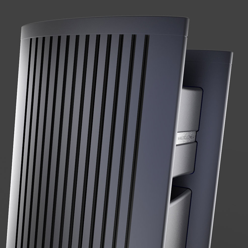
The Eclipse enjoys a completely redesigned input stage, further reducing non-linear effects and distortion. There are multiple independently tracking power supplies, superior internal shielding and higher output power. Finally the Eclipse amplifier offers a new, modern, ‘lighter’ take on the distinctive and award winning Halcro aesthetic. Even this contributes to better performance with the new, machined-from-solid casework reducing microphonics.
As things go around these parts, I’d love to hear one.
Specifications
Power
Power output into 4 ohms resistive > 350 W
Power output into 8 ohms resistive > 180 W
(Both channels driven, measured at 1kHz)
Distortion (Footnote 1)
- At full power output, all harmonic distortion orders
- THD <-120 dB (<1000 parts per billion) up to 20 kHz (100 kHz B.W.) at 350 W into 4 ohms.
- THD @ 1 kHz <-134 dB (<200 parts per billion).
- For sum of 19 and 20 kHz tones, each delivering 87.5 W into 4 ohms = peak power 350 W, resulting intermodulation products each <-120 dB relative to output.
- SMPTE-IM intermodulation products are each <-120 dB relative to output.
Inputs
There are three input modes:
- an unbalanced voltage mode input with an impedance of 22 kOhms
- a balanced voltage mode input with an impedance of 22 kOhms + 22 kOhms
- a minimal path voltage mode with an input impedance of 660 Ohms
The voltage gain of the balanced and unbalanced inputs is 30 V/V and for the minimal path mode is 15 V/V.
Noise
The equivalent input noise at the input is 5 nV/sqrt(Hz) for the voltage modes and 6 pA/sqrt(Hz) for the current mode.
Frequency Response
- 3Hz – 215kHz: -3db
- 7Hz – 90kHz: -1dB
(Measured at 1W output)
Slew rate limit
Maximum slew rate for both small signal and maximum output voltage is 100V/ms, (which is equivalent to a maximum output voltage at approximately 250 kHz.)
Power supply
- Active power factor correction minimizes mains current harmonic distortion
- 110V model operates from 100-120 r.m.s, 45-65Hz,
- 240V model operates from 220-240Hz r.m.s., 45-65Hz
- less than 100 parts per million mains hum and ripple on the amplifier power rails
- conforms with PFC and EU emission standards set for 2002
Overload (Footnote 2)
Recovery from hard overload at 20 kHz into 4 ohms is 1 ms.
Protection
The amplifier protection:
- is short-circuit proof
- has over current limiting
- has gradual power limiting if amplifier becomes too hot
- will cut out if a continuous DC offset appears on output
- will cut out if output current exceeds 12 A average continuously over a period of a few minutes
- is protected against most input overloads
The power supply protection:
- will cut out if most common faults are detected in the power supply (such as over-voltage, master clock at incorrect frequency, excessive temperatures)
- is protected against most mains transients
Components (Footnote 3)
For reliability, all semiconductors are at least industrial grade. All electrolytics are rated to 105°C. Only highly linear resistors and MKP10/FKP1 capacitors are employed in the critical audio path
- six-layer PCBs are used in the power amplifier to minimize stray magnetic fields and to accurately define voltages
- four-layer PCBs are used in the power supply to minimize E.M.I. and voltage transients, which improves reliability and power efficiency
Compartments
There are four heavily shielded compartments:
- a power supply unit
- an input amplifier section
- a power amplifier compartment
- an output filter compartment
Filtering
Series and common mode EMI filtering is present:
- on the mains input
- between the amplifier and power supply
High frequency filtering is present at the inputs and output.
Dimensions
Weight, 135 lb or 62 kg
Height, 31 in or 79 cm
Width, 16 in or 40 cm
Depth, 16 in or 40 cm
Shipping weight, 190 lb or 85 kg
Footnotes
- THD specifications of our typical best competitors are 200,000 parts per billion.
- Indicates no excessive negative feedback.
- “Industrial” grade is a higher grade than the “commercial” grade used by most manufacturers.